
Mighty Viper VTL-5255 ×31/65 5500MM Vertical Boring Mill With Live Milling (NEW)
Have one to sell?
ConditionNew
1 available
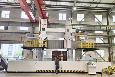
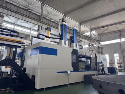
5500MM, Single Ram Live Tool ( Not Actual Photos ) This series of double-column vertical lathes is a high-tech mechatronic machine tool independently developed by our company, which incorporates cutting-edge contemporary design and manufacturing technologies. Adopting finite element analysis and optimized design methods, it complies with the latest national precision standards and is equipped with advanced functional components from both domestic and international sources. In terms of structural performance, it achieves heavy-duty cutting capabilities, boasting high dynamic and static stiffness, safe and reliable movement in all operations, a long service life, and high processing efficiency.
This is equipped with 2 tool rests, among which the left tool rest is a CNC tool rest that realizes two-axis linkage. Suitable for high-speed steel, cemented carbide, and ceramic cutting tools. It is applicable to the rough and finish machining of parts made from various ferrous metals, non-ferrous metals, and some non-metallic materials. It can perform processes such as turning inner and outer cylindrical surfaces, inner and outer conical surfaces, end faces, grooving, metric and imperial threads, and rotating curved surfaces.
Mighty Viper VTL-5255 ×31/65 5500MM Vertical Boring Mill With Live Milling (NEW)
Machining range Max machining diameter mm 5500
Max work piece height mm 3150
Max work piece weight T 50
Worktable Table diameter mm 5000
Table speed steps 2 Step
Table Speed range r/min 0.5~40
Max table toque kN·m 80
Left CNC Tool
post Max Cutting Force of the Tool post kN 45
Horizontal travel of the tool post mm -20 ~2800
Vertical travel of the tool post mm 2000
Feed Range of the Tool post mm/min 0.1~2000
Ram section size mm 280×280
Section size of tool bar mm 50×50
Vertical Tool post fast moving speed mm/min 4000
Right manual tool post Max Cutting Force of the Tool post kN 50
Horizontal travel of the tool post mm -20 ~2800
Vertical travel of the tool post mm 2000
Feed Range of the Tool post mm/min 0.1~2000
Ram section size mm 280×280
Section size of tool bar mm 50×50
Vertical Tool post fast moving speed mm/min 4000
Cross beam Max cross beam travel mm 2850
Beam lifting speed mm/min 350
Beam lifting motor power kW 22
Others Main motor power kW 75
Machine size mm 9000x7000x9000
Machine weight (about) Ton 115
Main motor CTB
Main motor drive CTB
CNC system, cables Siemens 828D or
Fanuc 0iTF Plus
Ac servo motor for CNC tool post Siemens
manual tool post servo motor CTB
ball screw Nanjinggongyi
gear HeBei KeXin (20CrMoTI)
bearing H.W.L
lubrication system HERG
hydraulic stations WuXi XinNaiSi
electrical components Schneider
coupling KTR/STS
lock nut Swift
Guideawy protective cover China brand
gear ring MASJWXNY(42CrMo)
oil cooler Tongfei
Electrical cabinet air conditioner tongfei
Traffic transmitter ELECALL
Reduction box NewStart
clamping jaws set 4
tool holder set 2
Foundation shims and anchor bolts set 1
Flatness of the worktable 0.03/1000mm (flat or concave), The tolerance increases 0.01 for every 1000 increase in diameter. Local tolerance: 0.01/ 300mm
Run-out of the worktable surface 0.01/1000mm, The tolerance increases 0.01 for every 1000 increase in diameter
Radial run out of the worktable surface 0.01/1000mm, The tolerance increases 0.01 for every 1000 increase in diameter.
Vertical movement of the beam to the table surface
a) Perpendicular to the beam
b) Horizontal to the beam a) 0.04/1000mm
b) 0.025/1000mm
Vertical tool post movement to the flatness of the worktable 0.02/1000mm
The roundness of finishing
cylindrical surface 0.015mm( On the standard specimen plane of a diameter of
500mm)
the flatness of finishing machining disc end face 0.04mm ( On the standard specimen plane of a diameter of
1500mm)
surface roughness (casting iron) Flatness, cylindrical surface:1.6μm conical, circular surface:3.2μm
Positioning accuracy 0.025/1000mm
Re-positioning accuracy 0.015/1000mm
1. Quotation validity: 30 days from the date stated as below.
2. Terms: FOB Long Beach Port, CA, USA
3. Delivery Time: 7 months after the deposit was confirmed.
4. Package: Steel or Wooden Cases for Long distance shipping.
5. Payment term: Wired (40% advanced payment and 60% balanced payment before shipping.)
Single Ram CNC Vertical Turning and milling
Max machining diameter:5500mm
Max workpiece weight:65T
CNC system: FANUC
Main motor: FANUC
Heidenhain X/Z axis optical scaled
Cooling through spindle 20bar
Chain type chip conveyor
Renishaw Tool presetter
Renishaw Workpiece measurement
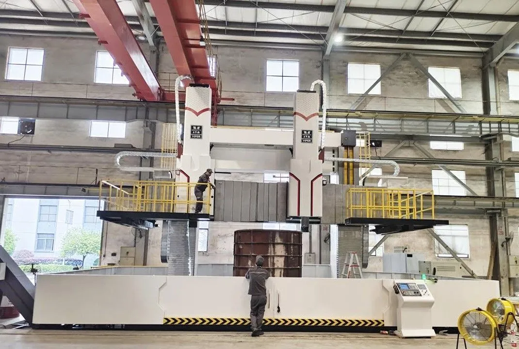
The gantry frame is composed of left column, right column, connecting beam, worktable and other components. The gantry frame is connected with the foundation to form a closed symmetric frame; it adopts high-strength and low-stress cast iron parts, which have sufficient rigidity and strength to ensure the long-term retention and stability of the machine tool's precision. Through finite element analysis and calculation, the dimensional structure and stress state of the gantry frame are optimized to ensure its sufficient strength and rigidity. A lifting box is installed on the upper part of the column, driven by a double-shaft extension AC motor, and through the transmission of helical gears, worm gears (material: ZCuSn10P1), worms and lead screw pairs, the crossbeam can move vertically on the column.
The column is equipped with double-sided stiffeners, including both horizontal and vertical ribs, to achieve the purpose of increasing rigidity.
The crossbeam is positioned in front of the columns. Driven by a double-shaft extension AC motor, it realizes vertical movement on the columns through the transmission of gears, worm gear-worm pairs, and lead screw pairs. There are 4 hydraulic clamping points at the rear of the crossbeam. Horizontal feed mechanisms for the left and right tool rests are installed at both ends of the crossbeam, and an oil receiving groove is mounted at the lower part of the crossbeam.
The guide surfaces of the joint between the crossbeam and the columns are covered with polytetrafluoroethylene (PTFE).
Pressure plates are installed on both the inner and outer sides of the left and right columns for the crossbeam, which reduces the deformation of the crossbeam in the released state and improves the stability of crossbeam lifting.
A steel nut component is installed at the lower part of the lifting nut. It is used to support the weight of the crossbeam when the T-shaped thread of the nut fails, playing a safety protection role.
The upper guide rail of the crossbeam adopts an inserted steel guide rail, which is unloaded by Japanese THK rolling guide blocks, featuring low friction, strong pressure resistance, and durability. The two sides of the crossbeam guide rail are protected by stainless steel metal shields, and a bellows shield is used in the middle.
The crossbeam sliding seat moves horizontally on the crossbeam, adopting a hydrostatic unloading guide rail pair. It is supplied with oil by a 20-point equal-quantity multi-head pump, and the pressure in each oil cavity is evenly distributed, ensuring stable operation of the tool rest.
The worktable is composed of a worktable, a worktable base, a spindle component, and a transmission mechanism.
(1) The worktable adopts a fixed-spindle type short-spindle structure. A set of high-precision (Class P5) double-row short cylindrical roller bearings is mounted on the spindle, with its inner bore featuring a 1:12 taper hole. By adjusting the radial clearance, high radial precision and a long service life of the worktable are ensured.
(2)The worktable spindle is of a short-spindle structure, equipped with high-precision double-row short cylindrical roller bearings to guarantee the radial runout of the worktable. The worktable guide rail adopts a constant-flow hydrostatic guide rail, supplied with oil by a gear pump that adapts to speed changes. The oil pump motor uses an AC motor to meet the flow requirements for different workpiece weights. Through a high-precision equal-flow gear oil divider, the required pressure oil is injected into the oil cavity, enabling the hydrostatic guide rail to achieve a good oil film thickness and high end face precision of the worktable under different workpiece weights. This ensures the hydrostatic guide rail has high oil film stiffness and small end face runout. When the oil film thickness is less than 0.04mm or there is no oil flow, a signal is sent in time to stop the worktable operation as soon as possible.
(3)The hydraulic device for the hydrostatic guide rail oil of the worktable and the lubricating oil of transmission parts is equipped with an oil temperature control device to ensure minimal oil temperature rise and thermal deformation of the worktable.
(4)The worktable surface is designed with standard T-slots and equipped with four sets of standard claws according to standards.
(5) material of the worktable gear ring is 42CrMo, with a hardness of 55±5HRC after quenching. All gears are made of 20CrMoTi, with quenched and ground teeth.
(6) Siemens or Fanuc encoder is installed at the center of the worktable to realize feed per revolution, threading, and constant-speed cutting.
4.4 Vertical Tool post
The equipment is equipped with two tool rests: the left one is a CNC tool rest controlled by a CNC system, and the right one is controlled by a PLC. The ram is made of high-quality forged steel through quenching and tempering as well as precision grinding, featuring high rigidity and hardness. The sliding surfaces between the ram and the tool rest sliding seat form a sliding friction pair with a low friction coefficient, and the guide surfaces are covered with polytetrafluoroethylene (PTFE). Therefore, the ram boasts high movement sensitivity, a long service life, and strong vibration resistance.
The vertical feed of the ram is driven by an AC servo motor, which drives the nut to rotate through a gear pair to realize the vertical feed and rapid movement of the vertical tool rest.
4.5 Main drive mechanism
The main turning drive and speed change mechanism are driven by a vertical spindle servo motor. The main motor is connected to the main gearbox via a synchronous pulley, and through two-stage vertical shaft mechanism transmission, the required speed range for turning is achieved.
The two-stage speed change is controlled by an electromagnetic slide valve to switch the oil circuit of the oil cylinder, enabling automatic hydraulic switching between two gears. The output gear meshes with the central gear of the worktable. To prevent pressure relief of the speed change oil cylinder, a pressure relay, accumulator, and hydraulic lock mechanism are installed in the control oil circuit to ensure reliable operation of the two-stage speed change. All gears in the gearbox undergo quenching and grinding processes to achieve high transmission accuracy and efficiency, while reducing transmission vibration and noise.
The gears in the vertical shaft gearbox have a large modulus, making them resistant to tooth breakage.
There are no bevel gears, resulting in low transmission noise.
All gears are made of 20CrMoTi, with quenched and ground teeth.
The gearbox lubrication adopts an adjustable oil divider. A flanged oil sight glass is installed for observing oil quantity, and a flow transmitter is also installed.
The guide rail lubrication of the worktable adopts a hydrostatic method. The hydrostatic lubrication for the worktable guide rail is supplied with constant flow through a multi-point gear oil divider. Lubricating oil is distributed from the 12 outlets of the multi-point gear oil divider to the 12 hydrostatic oil cavities of the worktable, causing the worktable to float. The floating height, ranging from 0.06-0.10mm, is achieved by adjusting the output flow of the variable vane pump.
The oil quantity for lubricating the worktable spindle bearings, large gear ring, and gearbox is adjusted by a variable displacement pump. It is adjusted and locked before the product leaves the factory and during maintenance, and must not be adjusted during use.
The safety pressure of the hydraulic balance system for the vertical tool rest ram is set to 5.0MPa by relief valve 30. It shares a pressure source (a variable vane pump) with the spindle speed change hydraulic system. The output pressure of the variable vane pump, which serves as the working pressure of the balance system, is adjusted to 4.5MPa.
The hydraulic station is equipped with a liquid level gauge and a temperature sensor.
Each oil circuit output point on the hydraulic station is fitted with a pressure sensor.
The hydrostatic floating of the worktable is equipped with power-off pneumatic protection to prevent scuffing damage to the base guide rail caused by sudden power failure.
4.7 Electric System
CNC system
The Siemens 828D system or Fanuc 0iTF+ is adopted. The system uses a human-machine interface with a 10.4-inch color LCD display, equipped with a PCU to complete the connection between the NC and the human-machine interface.
4.8 operation
The machine tool is equipped with a floor-mounted console, on which an operation panel and all operation keys of the machine tool are installed. It allows operation according to the programming of the processed parts and can also perform manual operation of required actions.
In addition, a set of handheld portable operation box is provided, which contains commonly used operation keys for the CNC tool rest and a handwheel pulse generator. Therefore, the machine tool is convenient and flexible to operate.
4.9 Cooling, protective devices and chip conveyor
The machine tool is equipped with a semi-enclosed protection. It is furnished with a cutting cooling system and an automatic chip removal system, where cutting coolant and metal chips are automatically separated by the chip conveyor; the metal chips enter the chip cart, and the cutting coolant flows into the cooling pump station.
The chip removal system of the machine tool consists of sloped bottom plates on both sides of the worktable and a chain plate chip conveyor at the front end of the worktable. Iron chips are transported by the chip conveyor installed at the front end of the worktable into the chip collection trolley, which is located on the side of the machine tool, improving the working environment, reducing work intensity and enhancing work efficiency.
5 Casting
Our company adopts the internationally advanced resin - sand casting process. The casting material is HT300, and it is tempered after casting. Tempering in the tempering kiln is carried out to minimize the casting internal stress. Vibration aging is performed before finishing to prevent the casting from deforming, thereby improving the accuracy of the machine tool.
5.1 Guideway surface processing
Quenching and grinding methods are adopted to ensure the precision of the guide rail surfaces, achieve an attractive appearance, and prevent scuffing damage on the guide rail surfaces.
We use cookies to improve your experience. Privacy Policy.